Determination of the Modulus of Rigidity
of a Wire using Maxwell's Needle
Measure the torsional stiffness of a wire by comparing the periods of oscillation of Maxwell's needle in two mass configurations.
Objective
Section 01Aim
To determine the modulus of rigidity η of the material of a given wire by the dynamic method using Maxwell's needle.
Learning objectives
After completing this experiment, students will be able to:
- Explain shear stress, shear strain, and modulus of rigidity.
- Describe the construction and working principle of Maxwell's needle.
- Measure the wire radius, needle length, masses, and oscillation time periods.
- Use two mass arrangements to eliminate the moment of inertia of the needle.
- Calculate G in pascals and estimate experimental uncertainty.
In the virtual lab, learners will be able to:
- Identify the solid-outside and hollow-outside configurations.
- Operate the Maxwell Needle simulation and record repeated readings.
- Verify that the difference of squared periods is used in the formula.
- Interpret the calculated modulus and compare trials.
- Recognize errors due to amplitude, timing, radius, and alignment.
Theory
Section 02Modulus of rigidity
The modulus of rigidity (or shear modulus) of a material is defined as the ratio of shearing stress to shearing strain, within the elastic limit.
For a cylindrical wire of radius r and length L, the torsional constant k of the wire is:
Here, r is the radius of the suspension wire, L is its length, η is the modulus of rigidity, and k is the torsional constant.
Principle of Maxwell's needle
Maxwell's needle consists of a cylindrical body suspended horizontally by a thin wire. When the needle is slightly twisted about the axis of the wire and released, it performs torsional oscillations.
Combining this with Eq. (1),
Experimental arrangement
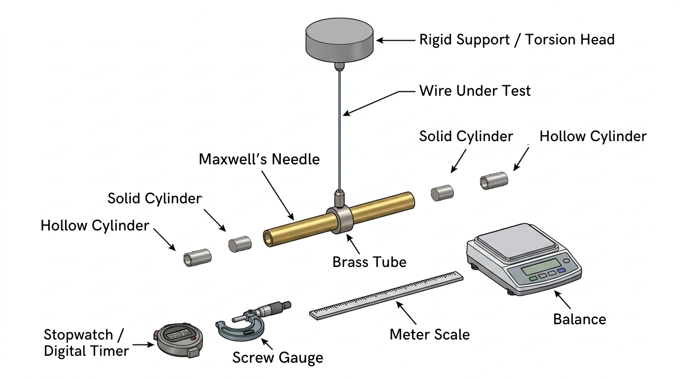
The Maxwell's needle arrangement consists of a hollow cylindrical tube, two identical solid cylinders, and a suspension wire. The solid and hollow cylinders are placed symmetrically about the axis of suspension in two different configurations.
Configuration I: The solid cylinders are placed farther from the axis of suspension, while the hollow cylinders are placed closer to the axis. Let the moment of inertia and time period be I1 and T1, respectively.
Configuration II: The positions of the solid and hollow cylinders are interchanged. Let the moment of inertia and time period be I2 and T2, respectively.
This arrangement permits the difference I1 − I2 to be determined without requiring the moment of inertia of Maxwell's needle itself.
Determination of the difference in moments of inertia
Let ms be the mass of each solid cylinder, mh the mass of each hollow cylinder, and L the distance between the centres of the cylinders. The distances of the cylinders from the axis of suspension are 3L/8 and L/8.
Relation between time period and moment of inertia
Therefore,
Formula for modulus of rigidity
From Eq. (1),
Substituting Eq. (7), we obtain the working formula:
Final working formula
| Symbol | Meaning |
|---|---|
| η | Modulus of rigidity of the suspension wire |
| L | Distance between the centres of the cylinders |
| r | Radius of the suspension wire |
| ms | Mass of each solid cylinder |
| mh | Mass of each hollow cylinder |
| T1 | Time period with solid cylinders at the outer positions |
| T2 | Time period after interchanging the cylinders |
SI unit of η: N m-2 (Pa).
Note: The final expression is written in the simplified and dimensionally consistent form:
Apparatus Required
Section 03Equipment
- Maxwell's needle with brass tube, solid cylinders, and hollow cylinders
- Wire under test with rigid support and torsion head
- Stopwatch or digital timer
- Screw gauge for wire diameter
- Meter scale for wire length and cylinder separation
- Physical balance for cylinder masses
Procedure
Section 04Experimental steps
- Measure the length l of the suspension wire using a metre scale.
- Measure the length L of Maxwell’s needle using a metre scale.
- Measure the mass of the solid cylinders mS and hollow cylinders mH using a physical balance.
- Determine the least count and zero error of the screw gauge before taking measurements.
- Measure the diameter of the suspension wire at several points using the screw gauge, applying the appropriate zero correction. Calculate the mean diameter and determine the radius r of the wire.
- Determine the least count of the stopwatch before recording the time measurements.
- Place the hollow cylinders on the inner positions and the solid cylinders on the outer positions of Maxwell’s needle. Suspend the needle by the wire and set it into small angular oscillations in the horizontal plane about the vertical axis. Record the time required for 5, 10, 15, and 20 oscillations. Calculate the time period for each observation by dividing the measured time by the corresponding number of oscillations. Take the mean of these values to obtain the time period T1.
- Interchange the positions of the cylinders: place the solid cylinders on the inner positions and the hollow cylinders on the outer positions. Again set Maxwell’s needle into small angular oscillations in the horizontal plane about the vertical axis. Record the time required for 5, 10, 15, and 20 oscillations. Calculate the time period for each observation and take their mean to obtain the time period T2.
- Substitute the measured values of l, L, r, mS, mH, T1, and T2 in the relevant formula for determining the moment of inertia and torsional rigidity of the suspension wire. Perform the required calculations using the logarithmic method, wherever applicable.
Maxwell’s Needle — Virtual Experiment
- Open the Simulation section of the experiment.
- Select Maxwell’s Needle – Torsional Oscillations to open the simulation.
- Click the Reset button to restore the simulation to its initial state.
- In the 3D View section, you can inspect the instrument from different directions. Hold the left mouse button and move the mouse to rotate the 3D view.
- The hollow and solid cylinders can be removed from or placed inside the Maxwell’s needle. To do this, click and drag the required cylinder from its holder (shown in blue) using the mouse.
- To take the readings, first place both cylinders inside the Maxwell’s needle. Then click the Hollow Out & Solid In button. Now click the Run button. The Maxwell’s needle will start oscillating and the stopwatch will start simultaneously.
- Count the number of oscillations and observe the time shown by the stopwatch. Stop the simulation after the required number of oscillations.
- Record the number of oscillations and the corresponding time in the observation table.
- Repeat the measurement for the required number of oscillations and record the readings carefully.
- Repeat the same procedure for different numbers of oscillations, such as 5, 10, 15, 20, etc.
- Click the Reset button again. Select the appropriate Hollow In & Solid Out configuration and take the readings for the solid cylinder placed outside and the hollow cylinder placed inside the Maxwell’s needle.
- Repeat the measurement procedure described in Steps 6–10 for the second configuration.
- Next, perform the wire-diameter measurement using the screw-gauge simulation. Click the Measure Wire Diameter button and note the required readings.
- Open the Result & Analysis section. Use the provided calculation tools to perform the required calculations and determine the moment of inertia (M.I.) of the given cylinders/wire as required by the experiment.
- Enter the calculated values in the appropriate fields and click the Generate PDF button to generate a PDF report of the virtually performed experiment.
Simulation
InteractiveObservation Table
Section 06Wire diameter and radius
Maxwell's needle time periods
Result and Analysis
Section 07Calculation
Use the mean readings in the expression below. Since the period is squared, accurate wire-radius measurement is especially important.
Record your calculation
Maxwell’s Needle Experiment – MCQs
Select the most appropriate answer.